Home › Unlabelled ›
Remote Control Light Switch Circuit Diagram : Remote Control Switch Circuit Ir Remote Control On Off Switch Circuit - By using this circuit you can easily control your home appliances using your tv, dvd player remote control or using a remote control circuit.
Remote Control Light Switch Circuit Diagram : Remote Control Switch Circuit Ir Remote Control On Off Switch Circuit - By using this circuit you can easily control your home appliances using your tv, dvd player remote control or using a remote control circuit.. This remote controlled switch circuit can control ac loads such as lights, fans etc through the remote handset of tv. If you know basic concepts of electronics, this circuit is. The transmitter section work as the main function of this remote control switch is to control any load like tv, fan, radio, light, etc. Hi friends,today in this video i have shown simple remote control ac light circuit | without ic part list: This remote gives approximately 150 meter coverage by extending the.
This is another useful circuit named ir remote control switch. If you know basic concepts of electronics, this circuit is. A versatile remote controlled switch circuit with diagram and schematic that can control any appliance designed using ir remote sensor ic tsop in this project, let's build a simple remote controlled switch for appliance controlling. Control an led with the remote control. The post discusses a simple ir remote control circuit which can be used for controlling many for controlling multiple gadgets using a single transmitter handset, many of the above modules may be constructed and integrated with the corresponding appliances for the intended switching.
Control Ac Light Using Arduino Arduino Project Hub from hackster.imgix.net Rf remote control circuit designed with 434 mhz ask (amplitude shift keying) transmitter and receiver, here ic ht12e act as encoder and ic ht12d act as decoder, this circuit is constructed with easy available components. It uses the 555 timer in the the circuitry can also be activated through torch and laser pointer. This device can be used to remotely control the speed of an ac fan and lights to switch it on or off. Automation circuitscircuits and schematics at fans can achieve remote control switch, speed control, remote control can also be achieved in other household switches. This is another useful circuit named ir remote control switch. Here is a complete design project from biltronix that allows you to. In this circuit, there is only one switch to operate. Direct your remote controller at the circuit.
Home » circuits » ir remote control circuit diagram.
A transmitter section and the other receiver section. Friends in this video i will show you how to make remote control switch for light/fan.simple remote switch circuit for on/off. This page contain electronic circuits about remote control circuits at category remote control circuit : Controlling of light by contents introduction circuit diagram components pcb layout advantage disadvantage applications improvement conclusion. Diagram showing how to read capacitance values of capacitors that use another system of notation on the actual capacitor. The post discusses a simple ir remote control circuit which can be used for controlling many for controlling multiple gadgets using a single transmitter handset, many of the above modules may be constructed and integrated with the corresponding appliances for the intended switching. I used a protoboard and the result is in the photo below. As shown in the circuit diagram, the ir receiver output pin is connected to arduino external interrupt pin (pin number 2), that means when a button is pressed (from the remote control) the arduino starts reading the ir signal immediately. And also a remote will be there 1.2.3. Ir (infrared) remote controlled switch circuit diagram for light/fan appliance. However, physical contact with switches may be dangerous if there is any shorting. We have used ic 4017 to convert it into a push on. By using this circuit you can easily control your home appliances using your tv, dvd player remote control or using a remote control circuit.
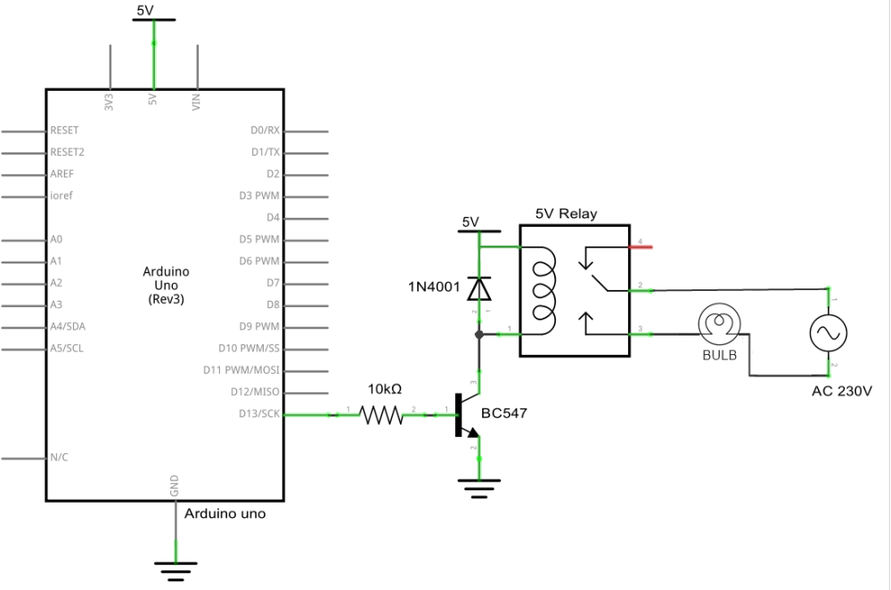
As shown in the circuit diagram, the ir receiver output pin is connected to arduino external interrupt pin (pin number 2), that means when a button is pressed (from the remote control) the arduino starts reading the ir signal immediately. Remote control switch for light and fan for circuit diagram go to akvtechnical.com. The receiver circuit is similar to a latching switch which on and off the output alternatively for each triggering. Adjust vr1 and vr2 to set the sensitivity of phototransistors at the particular light. Direct your remote controller at the circuit.
How To Make Light And Fan Switch Remote Circuit By Ic Cd4017 At Home Remote Circuit Youtube from i.ytimg.com A transmitter section and the other receiver section. If you know basic concepts of electronics, this circuit is. The circuit is an electronic switch. This touch switch circuit diagram is built around a 555 timer by making use of the default properties of the pins of the 555 timer ic. Ir remote control for controlling home appliances can be easily made using decade counter cd4017, 555 timer and tsop1738 infrared receiver. Output a control signal suitable for relay depending on the light level. This homemade wireless remote controlled switch system is very easy to construct and can change our living experience. However, physical contact with switches may be dangerous if there is any shorting.
This touch switch circuit diagram is built around a 555 timer by making use of the default properties of the pins of the 555 timer ic.
Automation circuitscircuits and schematics at fans can achieve remote control switch, speed control, remote control can also be achieved in other household switches. Automatic rainbow staircase lighting by magicmanu in leds. The design of the touch switch circuit diagram is very simple. This remote controlled switch circuit can control ac loads such as lights, fans etc through the remote handset of tv. A versatile remote controlled switch circuit with diagram and schematic that can control any appliance designed using ir remote sensor ic tsop in this project, let's build a simple remote controlled switch for appliance controlling. Controlling of light by contents introduction circuit diagram components pcb layout advantage disadvantage applications improvement conclusion. Press a rarely used button 10 times until the relay switches. Ir (infrared) remote controlled switch circuit diagram for light/fan appliance. The transmitter section work as the main function of this remote control switch is to control any load like tv, fan, radio, light, etc. In this remote controlled switch circuit we are using tv remote to on/off the ac light by pressing any button of remote, and using the tsop1738 at receiver circuit is connected to ac appliance via relay, so that we can control the light remotely. Control an led with the remote control. Rf remote control circuit designed with 434 mhz ask (amplitude shift keying) transmitter and receiver, here ic ht12e act as encoder and ic ht12d act as decoder, this circuit is constructed with easy available components. Sonic remote control light switch circuit (1 ).
Diagrams are for12v operation and there are high side remote controlled lamp dimmer: Automatic rainbow staircase lighting by magicmanu in leds. In this remote controlled switch circuit we are using tv remote to on/off the ac light by pressing any button of remote, and using the tsop1738 at receiver circuit is connected to ac appliance via relay, so that we can control the light remotely. The block diagram of an ir remote switch consists of two sections: By using this circuit you can easily control your home appliances using your tv, dvd player remote control or using a remote control circuit.
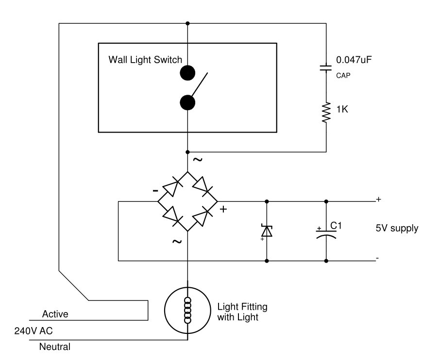
Remote Controlled Light Switch Retrofit With Manual Override And No Extra Writing from www.forward.com.au As shown in the circuit diagram, the ir receiver output pin is connected to arduino external interrupt pin (pin number 2), that means when a button is pressed (from the remote control) the arduino starts reading the ir signal immediately. Normally home appliances are controlled by means of switches, sensors, etc. By using this circuit you can easily control your home appliances using your tv, dvd player remote control or using a remote control circuit. Direct your remote controller at the circuit. Here the circuit arranged to toggle the output for each positive triggering at the clock input of the decade. I used a protoboard and the result is in the photo below. Remote control switch for light and fan for circuit diagram go to akvtechnical.com. Friends in this video i will show you how to make remote control switch for light/fan.simple remote switch circuit for on/off.
This remote controlled switch circuit can control ac loads such as lights, fans etc through the remote handset of tv.
And also a remote will be there 1.2.3. Normally home appliances are controlled by means of switches, sensors, etc. Hi friends,today in this video i have shown simple remote control ac light circuit | without ic part list: The design of the touch switch circuit diagram is very simple. This device can be used to remotely control the speed of an ac fan and lights to switch it on or off. Ir remote control for controlling home appliances can be easily made using decade counter cd4017, 555 timer and tsop1738 infrared receiver. Press a rarely used button 10 times until the relay switches. Home » circuits » ir remote control circuit diagram. Direct your remote controller at the circuit. Build your own rf remote controls & control stuff remotely! Automation circuitscircuits and schematics at fans can achieve remote control switch, speed control, remote control can also be achieved in other household switches. We have used ic 4017 to convert it into a push on. Arduino remote controlled light dimmer code: